A few days ago I held a workshop on do-it-yourself (aka cheap) surface mount electronics techniques at a Boston artspace/hackerspace called sprout & co (http://thesprouts.org/). This was organized through the Boston Arduino meetup group. Participants got to mount a tiny QFN-24 chip (a PCA9555 io-expander) onto a QFN breakout board and then we tested them by connecting them up to an Arduino. There was one bad chip; but once that was replaced everybody's boards worked!
Here are my notes from the workshop. If you did not attend, these notes are a good tutorial on how to get started cheaply! Also, if you'd like some of the QFN breakout boards, please contact me and I will sell you a few.
Surface Mount Tools (homemade/modified):
Toaster Oven:
Got mine from the dump. Keep it simple; you don't
need to mod it with fancy temperature feedback like some web posts suggest.
Hot air “pencil”:


$30 used heat
gun (ebay) with aluminum foil to narrow and speed the air jet. Secure the aluminum foil by wrapping steel wire around the nozzle. Shape the hole in the end by forming it around a pen with your fingers. This tool is indispensable for removing and replacing chips (rework), and works great!
Cheap plastic Mechanical Pencil:
Pencil lead solder paste onto pins;
eraser dabs off too much.
PCB Vice:
You can use any clamp like this. You can probably get one for less then $10 if you look around. Just drill a hole in your desk slightly smaller then the clamp bar and stick it in upside down.
Here it is holding the boards we made, with my breadboard-to-IDE-or-RJ-45 connector in the background.
Here it is holding the boards we made, with my breadboard-to-IDE-or-RJ-45 connector in the background.

But once you do this fairly often you'll want to upgrade to a Panavise.
Soldering Iron:
You CAN use a standard cheapo wide tip soldering iron for SMT rework -- even though you can't touch just a single pin, it is sufficient to heat a single pin.
However, knockoffs of the "Hakko 936" soldering iron are pretty cheap at $50; check Amazon or ebay. And they are all you'll ever need...
Tweezers:
You use these to hand "pick-and-place" chips. Buy them from a drugstore. But don't buy the cheapest pair you can find. Buy a set that looks totally overkill for plucking nose hairs :-) -- like they were milled out of a block of metal.

Magnifying glass/bright light:
You may need these to peek at the board as it is cooking, and for rework. I'm sure you can do it on the cheap. I have a "helping hands" for the glass:


Supplies:
Solder wire:
Get thin rosin core solder
Solder Paste:
Solder paste are tiny balls of solder in a flux mix that is viscous like toothpaste. It can be very expensive and require refrigeration. Don't buy that. Buy this Lodestar paste from DealExtreme. It does not require refrigeration, however, as a hobbyist you should refrigerate it so it will last you forever.
Flux:
Flux is a substance that cleans your PCB and lets the solder flow better. It is also available at DealExtreme. They often mis-name it "paste" but you'll know it is flux only because it won't be grey. Get "no-clean" or "neutral PH" (its almost all like that now).
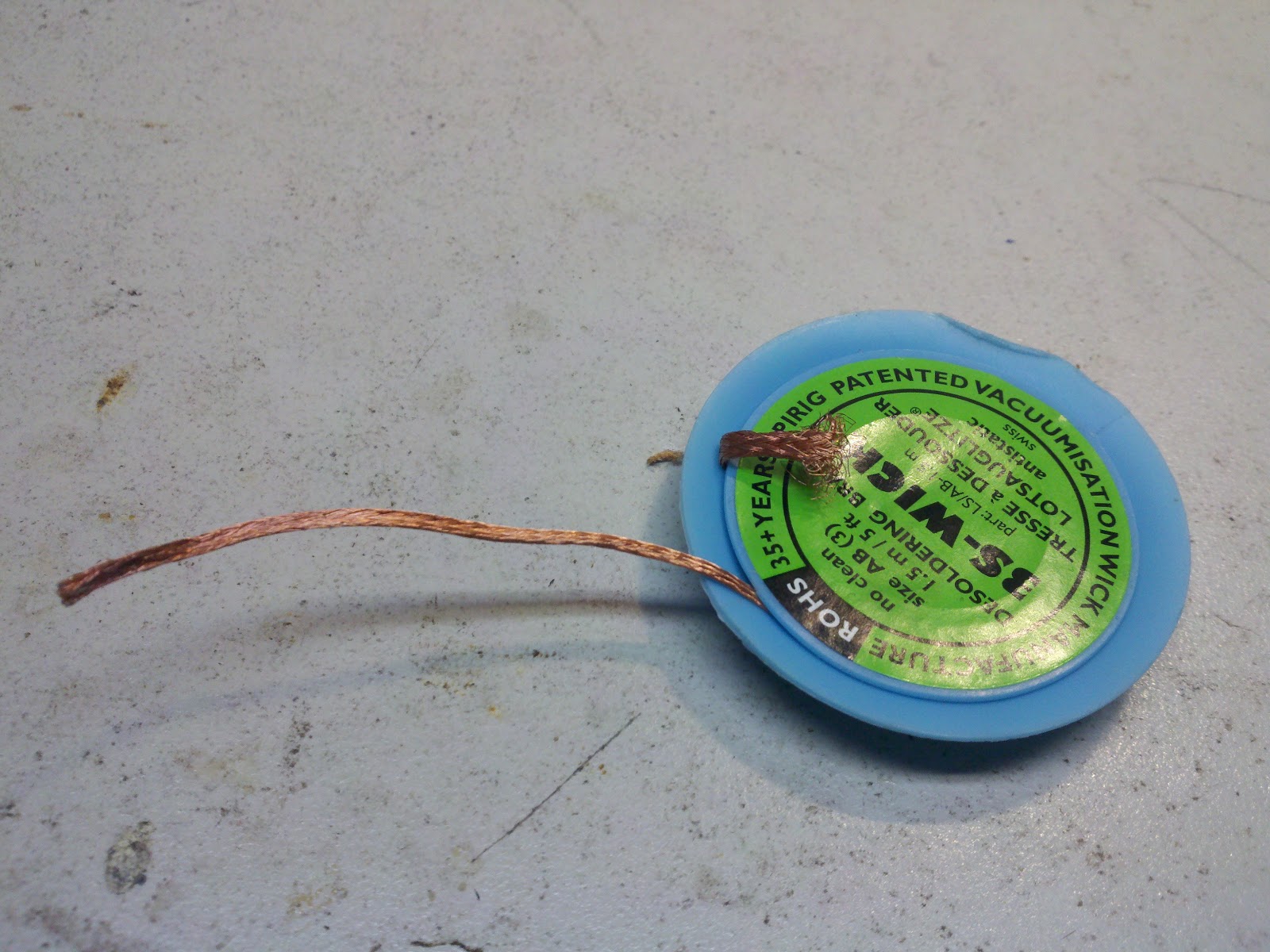
Solder Remover Braid:
This braid is necessary to remove excess solder when doing fine SMT work. Solder suckers don't work!

Step 1:
Use an oven to solder a QFN-24 part onto a breakout board.
Mix a TINY bit of solder paste and flux to about a 60/40 mix. You don't need much. Put any extra back into the container since it contains lead so its good to generate as little hazardous waste as possible...
Too much paste and the solder will not wick onto the pads (it will stay on the non-metal parts of the PCB or create bridges between pads -- "pads" are the metal parts of the PCB that you are trying to solder the chip's wires "pins" to)
Too much flux and the pins won't be soldered.
Apply with your mechanical pencil (click out the lead). For
tiny QFN leads, just draw your pencil straight across all the leads. That is, cover the entire surface including between the
leads. This is important so let me emphasize: Don't try to keep the paste out of the 6mil space between the leads! That is impossible & when heated the flux will cause the paste to flow to the pads anyway.
But if there is a center square pad, use the pencil to
draw around that pad to clean any paste that would bridge the center pad to a lead (it is
very hard to fix that issue).
You need to apply a thin layer. You should be able to see the shape of the pads under the paste, but they should be obscured. But if the paste goes on clear, with just a few "dirty" spots you have too much flux in your mix.

Next, put the chip on with tweezers. Positioning is not critical; you can be off by a half-pin in any direction. When hot, the chip will actually float on the flux layer and surface tension will actually cause the chip to be sucked onto the pads! But if you are off by more then a half-pin, the chip might be sucked onto the wrong set of pads.
Now bake your board. You need to bake the board in a particular fashion, but its not rocket science.
Here is an example provided by Kester paste. It works fine for any paste:
 Basically, you want to raise the board to 150C in a minute or two. Then wait for another minute or two so the entire board gets to that heat. This bakes out any water and lets everything expand (if you chip pops like a firecracker its ruined. You have too much water in those chips and need to bake the rest at low heat for hours to evaporate it out; its only ever happened once to me).
Next, you
bring the heat up to a max of 220-240C rapidly to melt all the solder
paste. Excessive exposure to this heat can harm the chips or melt
plastic parts so you want to keep this brief. At this point, use your
magnifying glass and a bright light to watch the paste on the board. It
will go from grey to bright shiny silver when melted (bubbling is just the flux moving around). Wait 10 more seconds after you see no more grey to make sure solder you can't see also melts. Then turn the oven off.
Now you have a choice. You can either wait with the oven door closed so the oven cools down slowly (as shown on the heat profile). Cooling slowly will mean there are fewer mechanical stresses on the board.
Or if you see any problems, you can open the oven door, pull out the tray and
reposition “tombstone” (sticking up) resistors and caps. Also if a chip is out of alignment (off by one pin for example), you can “tap”
the chip to make it position itself! When doing multiple bigger boards, you'll often find a few issues.
I'd imagine that while this cools the board faster, it is probably still less stressful then heating a portion of the board with your "air pencil". That is the only other way to reposition chips.
Debugging
Now that your board is baked and cooled, you need to visually inspect it. Look for bridges (2 pins connected) and unsoldered pins. A bridge will look more shiny then the other pins since it is a bigger solder blob. Unsoldered pins will look darker.
Unsoldered:
Apply a tiny bit of paste to solder pins. Heat the pin (and perhaps nearby pins) with an iron to melt the solder. Often you'll have added too much paste, so now check for bridges.
Bridges:
Use flux to cause the bridge to flow onto nearby pads/pins. This only works if the bridge is not caused by too much solder.
Use copper solder remover wire (braid) to
remove solder. I guess this is often misused. This is how you do it:
Touch braid to you can of flux to get a tiny bit on it)
Put the braid onto the bridge part so it complete covers it (and probably a bunch more pins).
Heat the braid by using the iron to press
it into the bridge where you want to remove the solder.
The braid won't work if its not hot!!! So heat it and cause its heat to melt the solder.
If the braid is at all silver, clip it and throw that part away; it has already sucked up solder.
Speed solder headers
Next we need to solder long headers onto the board. There is a fast technique to do a row of pins that I will show. Eventually you should be able to do about a pin per second or two.
First, clip/break the pin header so it contains the right number of pins.
Next put the headers in the solderless breadboard; and put the PCB on top. This gets them aligned correctly. Use the PCB to seat them into the breadboard. This will keep the board steady as you solder it.
Now its often good to solder the ends to make sure the PCB stays firmly seated against the pin header, but as you get better you can skip this step.
Now use the speed solder technique to do the rest. Here's a video:
Here I am doing pins on both sides of the iron, so heating 6 pins simultaneously. But you should stick with one side for now.
Use an overhand grip on the iron so it can be placed flush along the pins.
Heat 3 pins simultaneously.
Preheat pin -- using iron tip
Middle pin -- focus on soldering it
3rd pin -- continue to heat to make a good solder joint
I noticed most people using not nearly enough solder. Feed the solder so fast that there is a large constant blob of solder on the iron. This solder blob is essential to transfer heat to the pins. As you push your iron across the pins it will actually clean up this excess solder (if not, your iron is too cold, or you aren't using rosin core solder). Actually you may end up with a few bridges, but those are easy (and quick) to fix once the job is done. Just hold a "dry" iron against the bridge and it should grab the excess. And look for any holes you missed; as a beginner you'll have one or two!
Testing: Hook up the breakout board
Read the spec to hook up the board. Really. This is a great exercise and very important to get correct. Because if you are trying a new PCB, new software, and a new chip you want to make sure you get something right! :-) But ok, Ryan Feeney was kind enough to help you out with this image:

In this image, GND are the blue rows on both sides and 5v are the red ones (connect them to GND and 5v on your Arduino).
One other trick; if you don't have a handy 3.3v power supply, you can use a red LED to reduce 5v to 3.3v. This will work up to about 20mA; beyond that your LED will burn out so use multiples!
Testing: The sample sketch
The sketch I used is located at: http://i2cdevices.svn.sourceforge.net/viewvc/i2cdevices/latest/ioexpander/pca9555/pca9555.pde?revision=1
Someday I might actually put other i2c devices in there too! :-)
It should blink the LED.

Hot air rework exercise
Some of you got to do or see this, because we had a dead chip.
In this exercise we'll use the hot air "pencil" to remove a chip and then replace it with a new one.
First, use aluminum foil and metal boxes to cover and protect other chips (and plastic headers). Well, there is nothing really to protect in the breakout board except for the plastic vise jaws -- but for a "real" board you'll need this.
Heat the chip with slow motions of the heat gun. When the solder on the edges goes shiny, pluck/knock it off with tweezers.
If there is a lot of solder on the pads then clean it with flux and solder remover. Put a little more paste on the pads.
Touch the new chip in the flux can to just get a TINY bit of flux on its pads
Place the new chip right near, but not on, the pads. This will cause the chip to heat up with the pads. The chip's leads have to be hot enough to melt the solder or the solder won't stick to it! Its the SMT equivalent of a "cold" solder joint.
Reheat with the hot air "pencil". When the solder melts (it goes shiny) it should wick to the pads so there is no bridges. If there are bridges you have too much solder or not enough flux. When it wicks correctly, tap the chip with tweezers to move it into place. You should see it "snap" or "pop" into place as the surface tension of each pad/lead pulls the chip. Heat for maybe 10 more seconds to make sure all the chip's leads were hot enough and then you are done!
Thanks! Please go forth and build open source hardware!!
what a mind blowing posting done by you buddy. Thanks for sharing it. I want more posts like this by you in future
ReplyDeletesolder saver machine
| production indirect material
It's so important to realize that every time you get upset, it drains your emotional energy
ReplyDeleteWhat you feel inside reflects on your face. So be happy and positive all the time.